Showing posts with label Layout Construction. Show all posts

Saturday, January 8, 2022

Test Fit

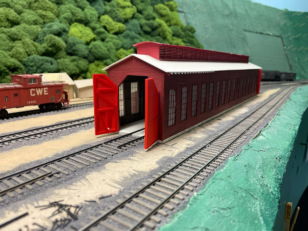
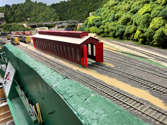
 Time for a test fit. The ties and rail have been removed, the ballast has been scraped up, and holes have been drilled for the wires for the lights. It appears that everything will fit as intended.


Now back to installing the 3,468 rafter ends along the roof overhang. And the clerestory still needs to be weathered. As can be seen in the photo below, the structure will dramatically change the overall appearance of the engine terminal at Nelsonville.


I'm anxious to see how it will look with the lights on inside. Stay tuned.

Friday, November 12, 2021

The Engine House at Nelsonville

 Since the first time I saw a picture of the single stall engine house on the C&O at Martin, KY, I've wanted to build a model of it. In fact, the engine terminal at Nelsonville was planned around a single stall structure. Over the years, I've collected a significant number of photos of the building. I found plans for the structure in the November 1986 issue of Mainline Modeler in the CD collection of C&O MM articles that was produced by the C&O Historical Society a number of years ago. But what was odd was that the drawings by Julian Cavalier only showed the end of the building and a cross section showing the interior framing. It finally occurred to me that the side elevation would have been a fold-out page and that's why it wasn't included on the CD. I put out a request on the internet and eventually found someone who scanned the rest of the drawing for me. Around this time I also found out that Minuteman Scale Models was offering laser cut windows and doors for the building. I quickly ordered them, along with the Evergreen siding that I would need for the project. I also made a drawing of how I would tackle the long louvers in the clerestory on the roof. Then I put everything away and wondered off to another project.

Fast forward ten years and the inspiration finally came back around. It arrived in the form of Neil Schofield's beautiful work on a typical New England barn. Looking at all of that bright white Evergreen styrene and windows got the creative juices flowing. You can see some shots of Neil's barn here on the Model Railroad Hobbyist forum: CP Rail's Newport & Lyndonville Subdivision | Model Railroad Hobbyist magazine (model-railroad-hobbyist.com). So I got out all the plans and information, reviewed all of the pictures, and got started. The picture below shows the progress on one of the sides along with the elevation drawing.


While working on the sides, I also started on the louvers. My original plan was to build a long strip of stringers for the individual slats and then cut them to size. The drawing below shows how this would be accomplished.


It quickly became apparent that there was no way I was going to be able to cut the stringers into 4" wide strips. Do you know how wide 4" is in HO scale? So it was on to plan B. I thought I might be able to place 2x6's at an angle on 2x4's and build up the louvers individually. I made a jig to hold the 2x6's at a 60 degree angle while the glue dried and used a small piece of basswood to provide spacing between them. You can see the initial setup below.


While the spacing looked good, it seemed as though gluing the 2x6's to the 2x4's on the edge wasn't going to provide a very sturdy sub-assembly. So I came up with plan C. I thought I could glue small pieces of 2x3's to 2x6's and build the louvers up in this manner. The photo below shows the results of the test.


There were several things wrong with this approach. First and foremost, there was simply no way I was going to be able to build the louvers this way. I don't have enough time left in my life. Secondly, they just didn't look right when held at the angle that they would be mounted on the building. So it was on to plan D. 

I had given up on the idea of building louvers that you could actually see through. It seemed the only solution was to construct them as a solid structure and make them appear as though there were openings in them. I took piece of 2x12, glued a 2x2 to the edge, and then started building a jig. It seemed as though this just might work. Paint the area between the louvers black and it would help hide the fact that you couldn't actually see through it. The photo below shows the results.


Eventually I finished the jig and it had eight louvers in it. But the section was small, gluing the 2x2's to the 2x12's was a pain, and it became clear that this wasn't going to be a very fast way of constructing all the louvers. And I was struggling with how to make these pieces into all the sections that would be needed to span the length of the roof. So now what?

As I was working on the wood jig above, I moved the assembly from plan B out of the way. I was getting ready to pitch it when I noticed that it was pretty sturdy. And when I flipped it over, it looked really good. So I thought there's no harm in adding a few more boards to it. Once I got going, I figured out the best way to add the 2x6's and the process began to go quickly. Most importantly, when the piece is flipped over, the louvers look great! And it would be relatively easy to connect these sections together. The photo below shows the progress using this method.


I got pretty discouraged at various times while trying to figure out the louvers. But fortunately, I stuck with it and didn't pack the whole project back into a box. It now looks like there just might be an engine house at Nelsonville in the not-too-distant future!

Friday, November 13, 2020

"Cause there's a fat man..."

No, not in the bathtub, but in the railroad room. During a recent op session, there were several instances of turnouts being thrown inadvertently. From all available evidence, it appears these were the result of a crew member bumping up against one of the pushbuttons on the panels. It one instance, it caused a massive derailment of a westbound MT coal train. And in fact, one crew member wrote up an occurrence, stating that he had actually observed a protruding belly commit one of these infractions.

The unnamed crew member who observed the pushbutton faux pas suggested a possible solution to the problem. His idea was to make clear cover with finger holes for the pushbuttons. I had some leftover Lexan clear plastic from a previous project, so I got to work.

The first step was to print out a copy of the panel to use as a template. I then measured the distance from the top of the pushbutton to the panel, substracted the width of the Lexan, and made stand-offs from Evergreen styrene tubing. Add some nuts and bolts and you have what you see below.


A close-up view of the Panel Protector (patent pending) shows the distance between the cover and the top of the pushbuttons.


I need one more of these for the panel at Summit Springs. Crews working the mines there need to lean in a bit to reach the cars and it would be easy to bump one of the pushbuttons while working a cut of cars. 

Now I just have to hope that the fingers of the fa.. er, waist challenged crew members will fit through the holes in the covers!

Saturday, October 3, 2020

Introducing... Hardy Coal Sales!

Some time ago, Anthony Hardy sent around a photo of a unique operation in the CSX yard at Ravenna, KY. Here's the photo along with his description:


Basically though what the operation consisted of was an old backhoe that permanently sat on an flatbed truck with no doors and beat up dump truck. And of course a siding.

CSX had a weigh in motion scale at Pryse about 4-5 miles from Ravenna yard. Sometimes they'd catch a car that was overloaded. Not every train...but somewhat a common occurrence. Just like a bad order, those cars had to be set out and corrected before they could continue.

Yard crew would work the train to pull the overloads, then set them out on the siding, which of course the crews referred to as "the overload track".

A local contractor, last name was Ballard, used the rear scoop from the backhoe to pull enough coal from the car to bring it into compliance. The coal was put in the old dump truck, then dumped on site. The dump truck was not used on the road, just onsite. There wasn't even a windshield in the dump truck.

My understanding is that the contractor was given the coal in exchange for making the car 'legal'. After enough was collected, they would sell the coal, bring in a tractor trailer truck, and bring a front end loader, and load out 2-3 truckloads of coal. I don't know who they sold it to...probably spot market stuff. I never saw them load it back into hopper cars, but that would be definitely plausible for shipment.

I also did see one time a centerbeam flat car loaded with fabricated i-beam floor joists spotted there. I don't know if the car was overloaded or if it got set out for some other reason but I can see where any heavy bulk load 'could' be overloaded. That was the only time I ever saw anything besides a coal hopper spotted there.

The other interesting thing was when the cars were lightened, many times they were part of a privately owned unit train. However, they would not get tied back on to that train next time it came through. It normally would leave via the one regular mixed freight that originated at Ravenna. So you'd see one or two aluminum rapid discharge cars leaving on a mixed freight.

It was a neat little operation for sure!


Of course, something like this just screams to be modeled, and I had planned on doing just that. The biggest challenge was finding the right backhoe and truck for my 1976 era. I spent some time searching the Internet but was unable to find anything that would work. Then Anthony came to my rescue with a picture of a backhoe made by GHQ Models and a link to their website. While the company is primarily a manufacturer of wargame models, they have a very nice line of HO scale kits of construction and farming equipment. Here's a link to the website: https://www.ghqmodels.com/ . I promptly ordered the backhoe kit and the project was on!

For the truck, I have a collection of old Roco military models that belonged to my father. One of the deuce and a half trucks seemed to be the perfect candidate as you could often find those in all types of service after they were sold by the military. Several modifications were made to the truck. The front axle was moved forward slightly in order to more closely match the prototype appearance and the sides of the bed were cut back to accommodate the outriggers. 

Modifications to the backhoe included removing the arms for the front bucket. As can be seen in Anthony's photo, the bucket has been removed and the front wheels have been turned in order to get the backhoe as far forward in the truck bed as possible. The photo below shows the truck and backhoe after being painted.


Next, the equipment was weathered using artist's oils and turpenoid. The pieces above were weathered separately as I wanted to make sure I could get into areas that might be blocked or difficult to reach once the vehicles were assembled. The photo below shows the results.


Finding a location for the operation was the easy part. There was an area of North Pierce that had never been finished because I couldn't decide what to do with it. One idea was to add an old boxcar as a storage shed. I also considered adding another building of some sort. And I was never really happy with the way the scenery around the truck loader turned out. There just wasn't enough coal on the ground around the structure and the tracks. The photo below shows how the area looked.


This area would be perfect- enough room for the equipment and coal on the ground and a place to spot a loaded hopper on the spur to the tipple. So the next step was to redo the scenery in the area. I used a combination of different colored grouts and real coal for the ground cover. The photo below shows the completed scene.


And here's a closeup of the truck and backhoe. Note that the outriggers have been added to keep the whole mess from tipping over!


Of course, there has to be some kind of paperwork for the crews alerting them to the overweight cars. Using the template I have for waybills, I made up some "OVERWEIGHT" inserts that can be slipped into the plastic waybill sleeve. The photo below shows a typical coal waybill along with one that has been marked as overweight. Note that it includes where the car should be set out along the line and the location at North Pierce with the TIBS alpha numeric code (Hardy Coal Sales N16). Crews will now need to be on the lookout for Overweight cars in addition to Bad Order cars


The photo below shows the MT's spotted at the tipple and the first loaded hopper ready to be relieved of some coal.


As for the name of the operation, it seemed only appropriate to call it Hardy Coal Sales. After all, it would never have happened without Anthony's photo, background info and help in finding a suitable backhoe. And if you know Anthony, then you know he has a wonderful sense of humor. When he originally passed around the email, he titled it "Ballard's Coal Scooper Outer." So this operation, while formally named Hardy Coal Sales, will most likely be referred to by the crews as the Scooper Outer!

Monday, September 21, 2020

Bunk House Update

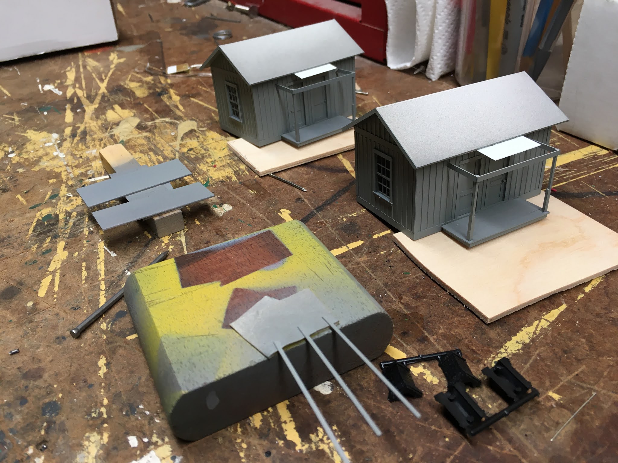
 Now that the sailboat is put away for the season, it's time to get back to work on the railroad. I did manage to get a few things done over the summer, including some progress on the bunkhouses mentioned in a previous post. The photo below shows the current state of completion.


The tabs over the porches will be used to attach the porch roofs which can be seen in the middle left of the photo. The 2x4's that were painted the same color as the bunk houses will be used for the porch railing. The next photo shows the scratch-built doors.


These two structures will be located to the west of the yard office at Nelsonville. The photo below shows the area. The back of the buildings will be supported by posts in the same fashion as the section houses at Quinnimont. 


And now for a sneak peak at what will be a new "industry" on the railroad. 


More to follow on this exciting project in the near future!

Friday, July 10, 2020

Inspiration- Part 3

Most of the scenes and structures on the railroad have been copied from the prototype in some form or fashion. It has often taken me a long time to find the right combination of structures and/or scenes in order to finish a particular area of the layout. By copying the prototype, at least to some degree, the scenes end up looking plausible and "right" in my eye. I've never been able to create something out of whole cloth that achieved the look I wanted.

A case in point is the collection of yard structures at Nelsonville. There has been an old wooden coach there for years that serves as the yard office. It's a wooden model that my Stepfather built many years ago. I painted it grey, added some roof details, and was planning to blank some windows, add a window air conditioner, and other details but lost interest at some point. You can see the structure here at the beginning of the video: https://www.youtube.com/watch?v=GlArolLdoXw. The intent with this structure was to copy a similar scene at Sproul, WV on the C&O. But there's just too much wrong with the old car to make it work. So the plan now is to copy the yard office at Elk Run Jct. which can be seen in the photo below by Jonathan Spurlock. The shanty on the right in the picture has already been built and is in service at Nelsonville.


There will be several structures along the tracks to the west of the yard office and I've been kicking around ideas for this area for a long time. I looked long and hard at the structures in the yard at Thurmond, WV but came to the conclusion that there just wasn't enough room. Also, the track by the yard office is a runner and not a RIP track like the one in Thurmond, so most of the structures wouldn't have been appropriate.

So next came the idea of some type of crew quarters. I have a number of photos and plans for C&O section gang houses, and these seemed like they might work. However, most of these are two room structures with an addition on the back. I would have to skip the addition as there isn't room for it. For that reason, I wasn't completely sold on this idea.

And then came the photo. Robert Slavy posted a photo of a bunkhouse at Quinnimont, WV on the C&O Fans Facebook page. I have never seen a photo of this structure before in any of the books I have on the C&O or in any of the articles on Quinnimont that appeared in the C&OHS Magazine. This was it- finally! And it was built  to the same design standard as the other structures I have already planned to use in the Nelsonville engine terminal!

As an aside, Robert Slavy has an incredible collection of photos that he took in and around C&O locations in West Virginia in the 1960's and '70's. He grew up in Pineville, WV and worked for many years in the region. He also has some great photos and videos of the Virginian Railway in and around Mullens and Elmore, WV. I met Robert at a Virginian Crazies weekend several years ago and he's a great guy.

Back to the bunk house. The picture below shows the structure sometime in the mid-1970's.


Note the board and batten siding so common on lineside structures on the C&O. And note the longitudinal board just above the window. This same style of architecture was used on many C&O buildings, including some of the ones in Hinton, WV. I scratch-built several of the Hinton structures based upon drawings by William Simonson that were published in Model Railroad back in the early 1990's. They can be seen in the photos below.


Two of the bunkhouses will fit perfectly in the space between the yard office and the motor car shed. Now all I have to do is get them built!

And, thanks Robert, not only for this picture, but also the many others that you have shared from your collection of C&O and VGN pictures. As many others have suggested, there's a book waiting to be written with all of your shots.

Tuesday, March 10, 2020

The Bartizek Brake

When I originally drew up the track plan for the railroad, I had absolutely no operating experience. I had read a great deal about track planning for operation, though, including John Armstrong's legendary book. Fortunately, most of what I had laid out originally works pretty well and what didn't I was able to change without much trouble. Except maybe the original west end staging...

One of the design issues that became apparent once I began operating was the grade in the yard at Nelsonville. The entire yard is on a grade of about 1.25% westbound. While this didn't seem like a lot during the planning phase, it's just enough to make it difficult for certain locomotives to push long cuts of cars up the tracks. And with advent of extremely free rolling wheelsets, holding cars on the grade has become a challenge. The solution to the lack of power was to replace the aging SW1200's with a GP7. The solution to holding cars on the grade is the Bartizek Brake.

My good friend Bob Bartizek is the owner and superintendent of the Pennsylvania & Western, a beautiful 3-rail, O-scale layout depicting the Pennsylvania Railroad in the early 1950's. Bob recently replaced a large number of his hopper cars with more accurate, and more free-rolling, models. And during a recent operating session, it became apparent that these cars weren't inclined to stay spotted at any location that had even the slightest grade. So Bob began to think of a way to make "brakes" to hold them in place. He discarded all of the usual ideas for various reasons. Then he hit upon the perfect solution- a small dab of ACC on top of the rail. A small blob is just enough to hold the car but not enough to impair movement over the track. And it's clear, so it's almost impossible to see. But most importantly, it's virtually maintenance free!

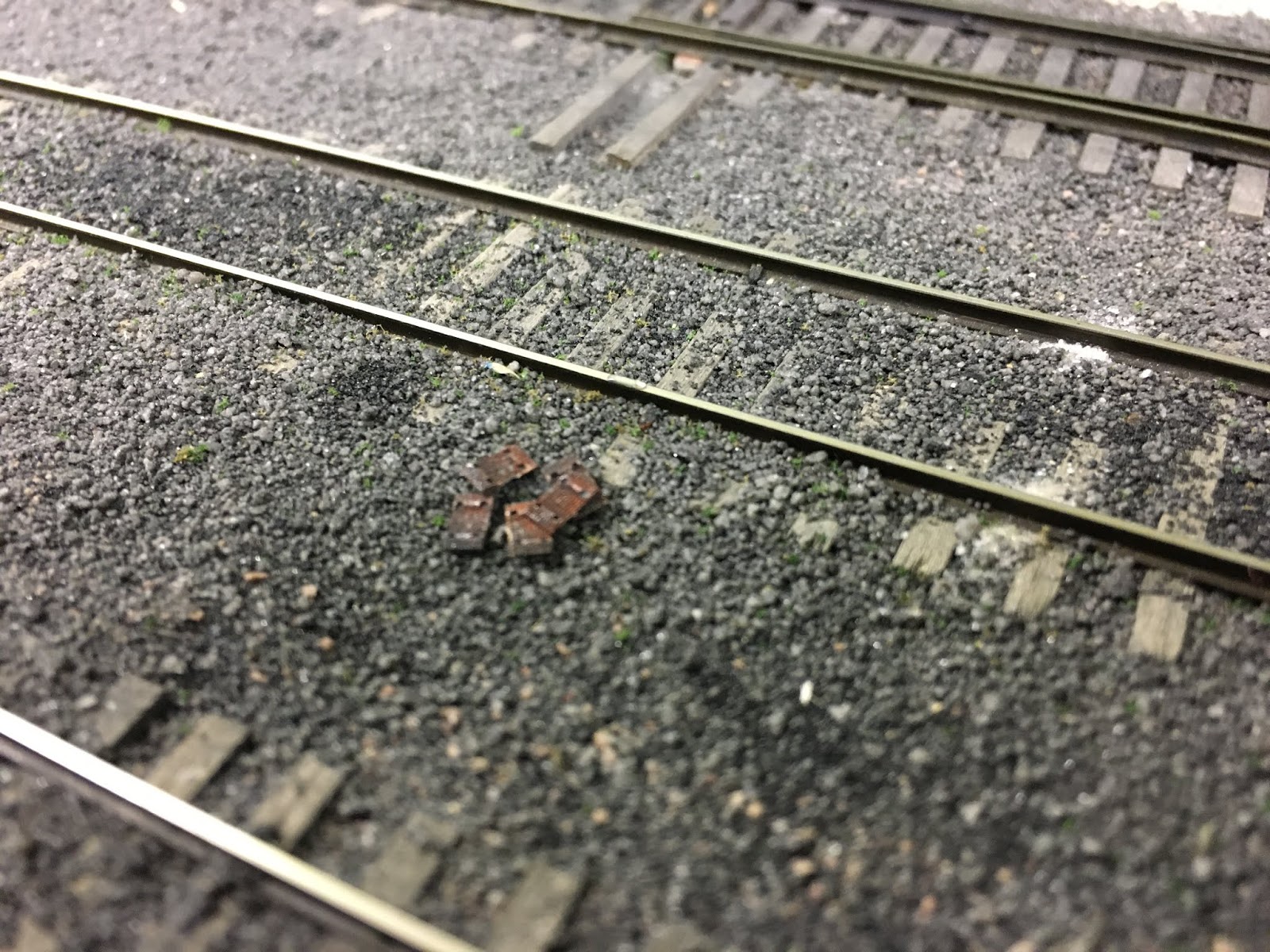
So armed with Bob's great idea, I finally had a solution to the brake problem at Nelsonville. The photo below shows the small dab of ACC on the rail near the west end of the yard.


Note the ties plates- the small blob is right above them. The tie plates will help the crews identify their locations (it's almost impossible to see them!). And there are "brakes" on one rail on each of the yard tracks and the siding at this location.

The next photo shows the brakes at mid-yard. A small piece of tie identifies the location of these brakes.


And the last brake is on the track near the east end of the yard. Once again, tie plates show the location.


These brakes are just a really great idea. No mess, no fuss, nothing to operate, easily replaced, almost invisible and work as advertised. Thanks, Bob! 

Monday, January 27, 2020

Bring on the rolling stock!

The final tracks have been laid in the west end staging yard. All of the Tortoise switch machines are in and hooked up and feeders have been run to all of the tracks. The photo below shows the results.


There are twelve tracks capable of holding trains and a shorter track that can be used to store protection power. The LV 628 and EL SD45-2 in the background are sitting on track 13.

Changes have also been made to the east end staging yard in anticipation of future expansion out into the crew lounge. The biggest change was removing a section of the upper staging yard that was over the ladder for the lower yard. The picture below shows the results.


It occurred to me that I would never be able to get to those turnouts when they need some tweaking with the upper staging yard built over them. And they will need some attention at some point- I've already learned that lesson. The expansion plan calls for the upper staging yard to be approached from the other end, so there will be plenty of room to make up for the lost section above. The upper yard could also have the ladder start at the west end above as there is room along the far wall to extend the shelving.

Another addition to the east end staging yard can be seen above- an LED strip. During the last op session, Randy Seiler suggested adding some LED's in order to improve visibility. He was kind enough to give me a 4' section and the results can be seen below.


Given the intensity of the light, it's almost impossible to get a good shot with a cell phone camera. But suffice it to say that the strip will provide more than enough light for the crews to see their trains. Thanks again for the tip and the strip, Randy.